The CMC104 Controller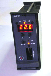
The CMC104 Controller
The CMC104 is a direct replacement for the Landis & Gyr RWF61.30 controller which is no longer available from the original manufacturers. As we understand it, the alternative offered by L&G is to re-wire part of the control cabinet in order to accomodate a new but physically different device.
For many users, this is not an attractive proposition, hence our own version of the RFW61.30. It is a direct replacement both physically and electrically and may be 'hot-swapped' with its equivalent L&G device. However it uses modern digital electronics unlike the original analogue-only device which dates back to the 1980s.
Also, at a price of £380 it is far more cost-effective than the re-wiring option.
General Description
The CMC104 comprises three temperature sensor inputs (B1, B2, B3) which conform to the L&G sensor specification:
Temperature (degr C) / Resistance (ohms)
0 = 1000
10 = 1045
20 = 1091
30 = 1138
In a typical application B1 measures the Return Air and controls outputs Y2 and Y3 according to an adjustable Set-point.
B2 measures the Discharge Air and is used as an over-ride to inhibit outputs Y2 and Y3 in the event of too low a discharge temperature.
B3 is available for later expansion.
The CMC104 includes three 0-10v outputs (Y1, Y2, Y3). The status of each output is indicated by one of three LEDs across the top of the front panel. If the low limit sensor (B2) detects that the Discharge Air is below the limit set (see below on how to adjust this) Y2 and Y3 outputs are inhibited and the relevant LEDs will flash at 1 second intervals (assuming that otherwise they would have been on).
Y1 controls heating and is adjustable for different site configurations. This output may be programmed in software as required.
Hysterisis
The temperature inputs are processed inside the CMC104 to smooth out short-term variations by averaging consecutive measurements. The processing also adjusts the value depending on whether the temperature is increasing or decreasing in order to avoid rapid changes in the controller output (hysterisis). However, the display always shows the ‘raw’ data from the sensor. This enables an engineer to check that the input is stable and not affected by interference from other equipment, for example.
P-band
This term describes how steep the adjustment of the output is
in relation to the input. The value of P-band is calibrated in
Degrees C. For example, if the P-band is set at 1, then the adjustment
is very steep and the output will immediately switch to 10v if
the Return Air is more than 1 degree above the Set Point.
A P-band of 16 gives a very gentle adjustment, meaning that the Y output will only reach 10v if the Return Air is 16 degrees above the Set Point. Other temperatures will give a proportional output voltage, eg if the Return Air is 6 degrees above the Set Point then the corresponding Y output will be 5v. Some rooms may benefit from a very low Set Point and a high value for P-band.
Settting the P-band
The bitswitch elements 1-4 are used to set a number between 1-16. Other bitswitches select options such as BMS network (see below).
The Set Point
The Set Point is set by pressing either the + or - keys. The first key press of either key does not change the Set Point but just switches the display to show the Set Point. The Set LED is lit to show that the display has switched to showing Set Point. The display will return to showing the room temperature after a delay of 5 seconds if no other key is pressed.
The Set Point may be adjusted between 15-25 degrees C in 1/2 degree steps.
The Set Point is used to calculate the Y2 output as described above and a second internal Set Point two degrees above the main Set Point controls the Y3 output.
The Mode Switch
The display may be switched to show the Discharge Temperature by pressing the Mode switch. Alternately pressing this switch will toggle the display between Return Air and Discharge Air temperatures. The Discharge temperature is indicated by the far right decimal point being lit. Note that there is a slight delay between pressing the mode switch and the display changing due to the fact that the display only refreshes an one second intervals.
While the Display is in Discharge Temperature mode, the + and - keys operate on the Low Temperature Set Point between 5-11 degrees C just in the same way as previously they adjusted the main Set Point.
Power Save
Under normal operating conditions the CMC104 is shut away in a cabinet and the numeric display is not visible. Therefore, to conserve power, the CMC104 switches to low-power mode if no buttons have been pressed for 2 minutes. The main display is blanked but the Y1, Y2, Y3 LEDs remain operational. All other functions operate as normal, including history logging.
To wake the CMC104 from its low-power mode, press the Mode switch.
Diagnostics
The CMC104 stores parameters such as set points in permanent EEPROM memory and the same memory is used to store a trend log of up to 24 hours of operation for later replay on a PC. To clear the memory and start recording, press Mode and + at the same time. To replay the data into a PC, press Mode and - at the same time. Normally one would clear the memory following a Replay of data. Replay on its own is non-destructive.
Each of the Y outputs is wired to this socket and may be monitored using a digital voltmeter, for example.
The diagnostics port is also used for upgrading software.
The CMC104 also replaces the RFW61.10 and RFW61.20 controllers - all inputs and outputs remain an integral part of the circuit board but are not addressed by software.
BMS Network
The CMC104 may be made part of an RS485 network in which case set points may be controlled centrally and room temperatures monitored using the Applied Microsystems CM55 BMS network (please enquire about other networks). The network interface requires a software update but no further modifications are necessary.
For more information please don't hesitate to call us by returning to the home page and clicking on the Target logo.